Why does a piece of paper fall slower when it is flat than when it is vertical?
While this question sounds simple, it is the exact starting point of automotive aerodynamics as a whole.
When falling flat, the paper experiences pressure drag. Air flows faster over the upper surface, creating low pressure, while flowing slower underneath to create high pressure; this pressure differential essentially "lifts" the paper.
When falling vertically, its projected frontal area is minimal, allowing air to bypass it easily and causing it to fall much faster.
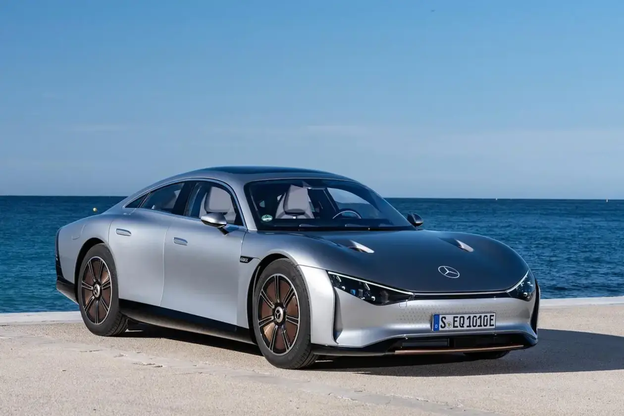
In essence, automotive aerodynamics does the exact same thing: controlling pressure distribution across the vehicle's bodywork.
No matter how streamlined a car is, once it is in motion, airflow will inevitably "detach" at certain points and "pile up" at others. An aerodynamicist's job is to constantly battle these areas of flow separation and high pressure.
First, let's ask a more fundamental question: when air flows over the bodywork, what is the velocity of the air layer in direct contact with the car paint?
The answer is zero. This is known in fluid dynamics as the no-slip condition, where the velocity of the fluid layer immediately adjacent to the solid boundary relative to that boundary is zero.
Between the zero-velocity wall and the free-stream flow, there is a transition zone where the velocity gradually increases. This thin boundary is the boundary layer. Within this layer, viscous forces transfer momentum from the free-stream flow to the slower-moving fluid near the wall.
The boundary layer exists in two states: laminar flow and turbulent flow.
In a laminar boundary layer, the streamlines are orderly, akin to school children walking in a neat queue. In a turbulent boundary layer, the streamlines become chaotic, resembling students rushing out of the school gate at dismissal.
One might assume laminar flow is superior due to its orderly streamlines and lower friction. However, a laminar boundary layer has a fatal flaw: its resistance to adverse pressure gradients is extremely weak.
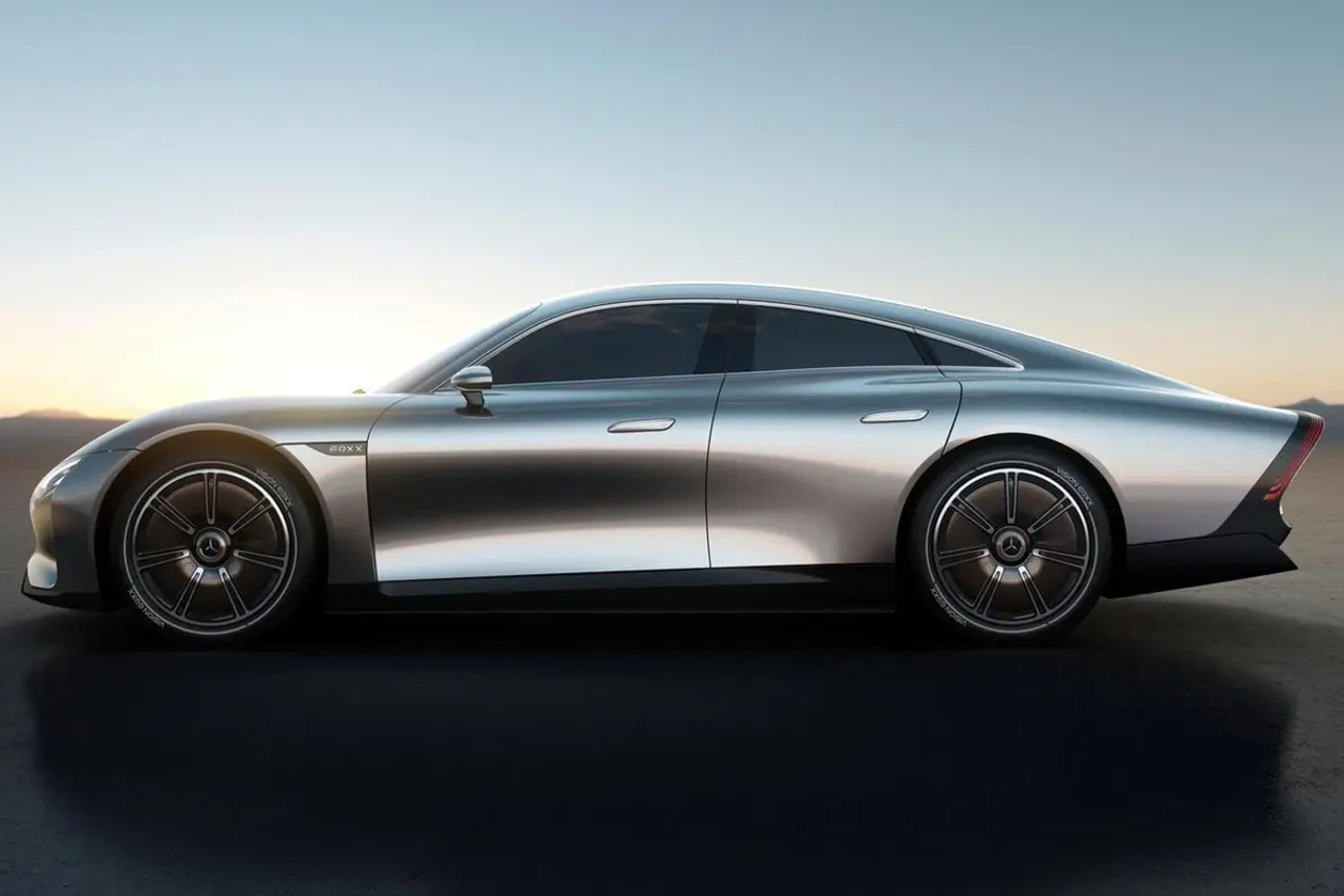
What is an adverse pressure gradient? As air flows from the nose to the rear of a vehicle, the flow passage expands, causing the velocity to drop and pressure to rise. This zone of increasing pressure is the adverse pressure gradient region.
The low-velocity fluid within the laminar boundary layer already lacks momentum; when it hits this gradient, it is like walking into a strong headwind—it quickly grinds to a halt.
What happens when it stops? Flow separation.
The separation point is where the normal velocity gradient of the fluid at the wall reaches zero. Once separated, the flow detaches from the surface, creating a massive low-pressure wake zone at the rear of the vehicle. This low-pressure pocket "pulls" the vehicle backward, generating pressure drag.
Consequently, engineers employ a seemingly counter-intuitive strategy: actively inducing the boundary layer to transition from laminar to turbulent flow.
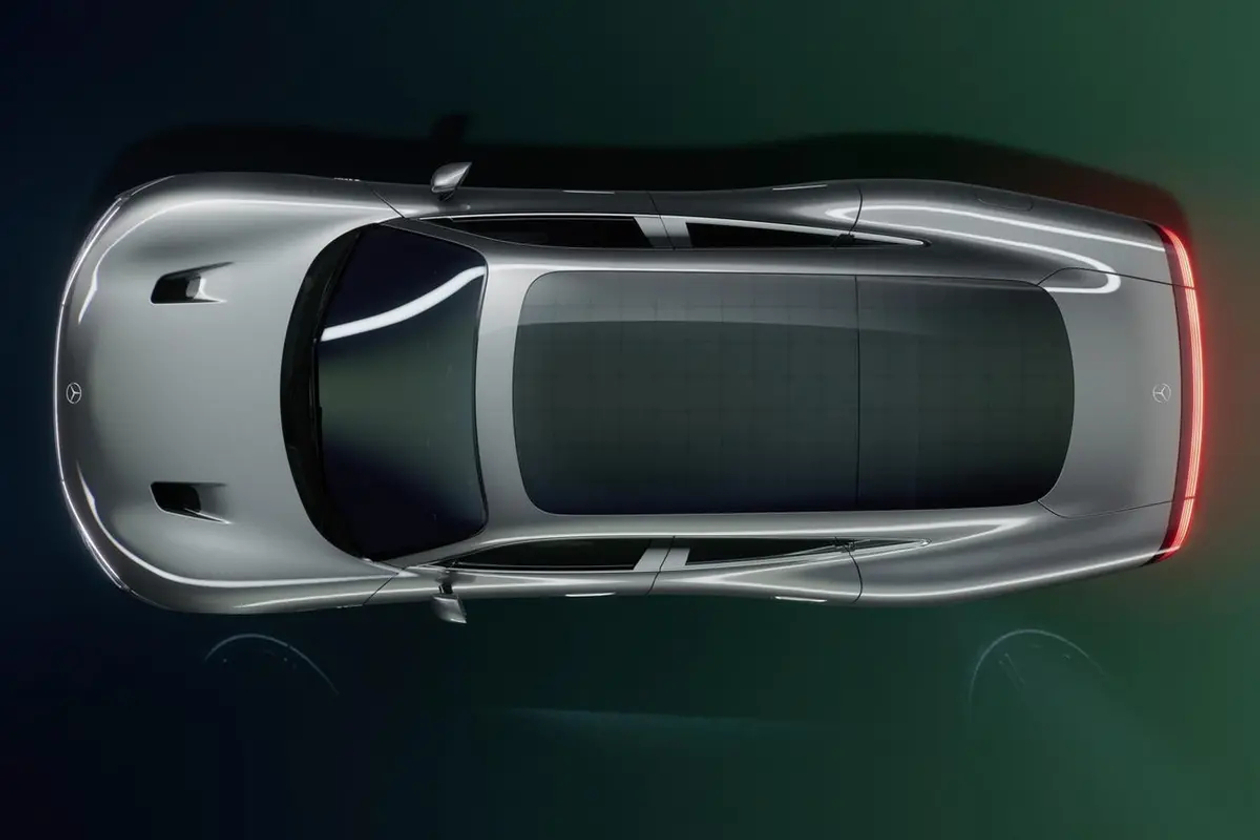
While a turbulent boundary layer creates higher skin friction drag, its internal turbulent fluctuations "energise" the boundary layer by mixing high-momentum air from the free-stream down to the wall. This allows the flow to remain attached longer against the adverse pressure gradient.
By delaying the separation point, the low-pressure wake zone shrinks, leading to a massive drop in pressure drag.
The slight increase in friction drag is far outweighed by the reduction in pressure drag. This is the same principle behind golf ball dimples, which trigger boundary layer transition to turbulent flow so the ball travels further.
How is this transition actively triggered on a car? The air curtains on either side of the front bumper are a prime example.
These ducts channel high-velocity air along the outer face of the front wheels, injecting high-momentum flow into the wheel arches. This reinforces the boundary layer against the adverse pressure gradient and delays separation.
A well-designed air curtain significantly improves flow attachment along the vehicle's flanks with virtually no drag penalty.
Another question: how does air behave as it flows over the roof?
Air is split at the vehicle's nose: one portion flows over the roof, another runs underneath the underbody, and the rest wraps around the sides.
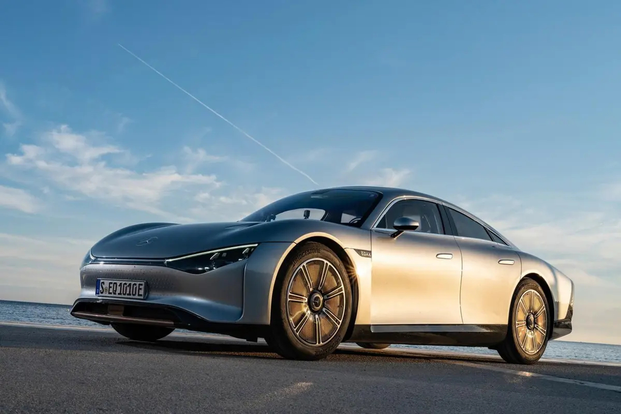
The air flowing over the top follows a "natural flow" path. It accelerates and drops in pressure over the curved roofline, then decelerates and gains pressure as it nears the rear windscreen.
The position of the separation point directly dictates the size of the trailing wake. The further rearward this separation occurs, the smaller the low-pressure zone and the lower the pressure drag.
However, the underbody flow introduces an even more problematic phenomenon: the underbody ground flow.
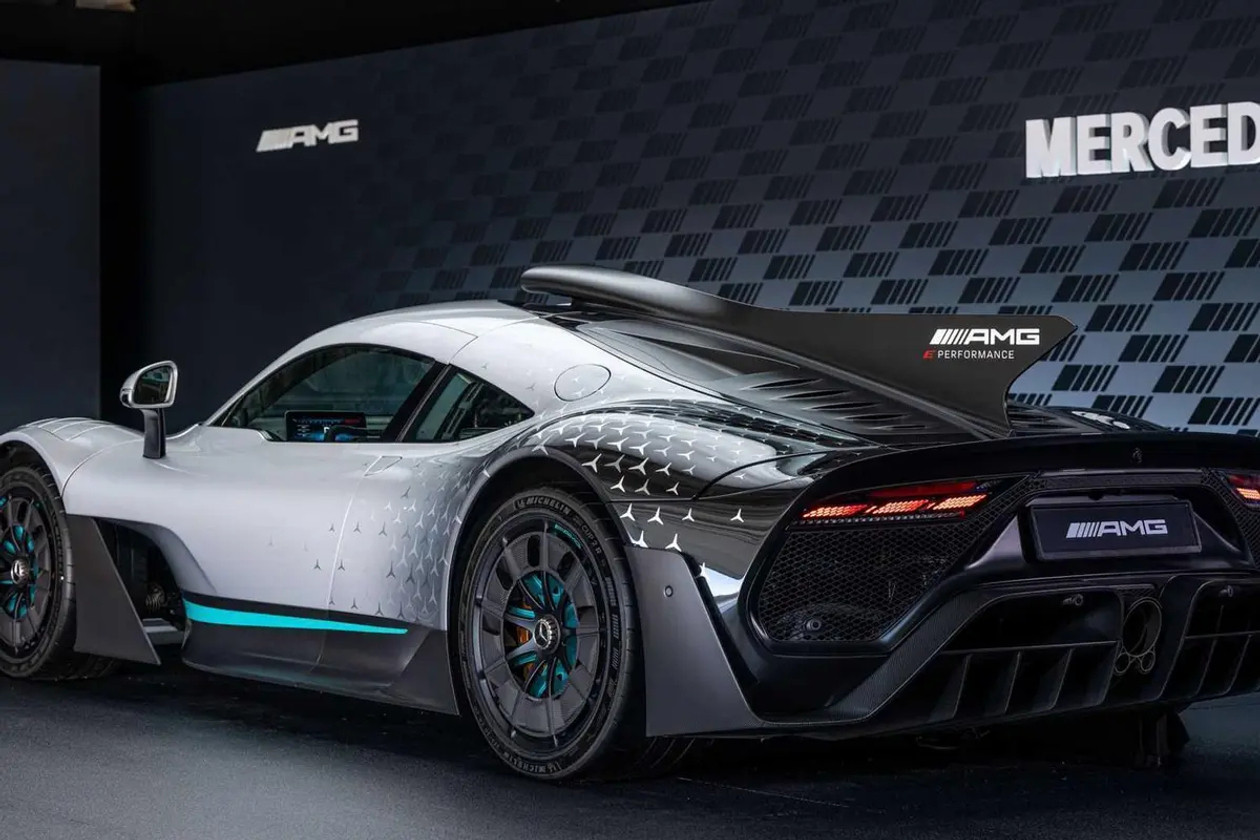
At high speeds, air ahead of the car is compressed, forcing a portion to "squeeze" through the gap between the front splitter and the road.
This underbody flow travels at high speed through the narrow space under the car. Subjected to double shear forces from both the road surface and the underbody boundary layers, this airflow loses energy and is highly prone to separation.
Once this flow separates, it creates a large low-pressure area beneath the chassis, which increases drag and robs the car of downforce.
Lowering the front ride height can restrict this underbody airflow, but excessively low ground clearance compromises daily drivability. Engineers must strike a fine balance.
Active suspension systems solve this by automatically lowering the ride height at high speeds, minimising underbody flow issues while preserving usability.
Where does most of an F1 car's downforce actually come from?
Most would point to the front and rear wings. But the real answer is that roughly 40% to 50% of Formula 1 downforce is generated by the underbody floor and the rear diffuser.
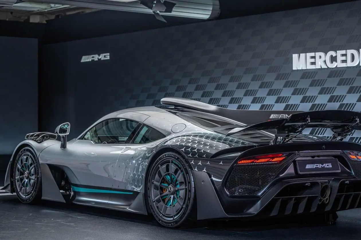
The operating principle of a diffuser is straightforward: the Venturi effect.
Air accelerates and drops in pressure through the narrow underbody channel, then decelerates and recovers pressure in the expanding section of the diffuser.
The critical point is the lowest pressure zone at the diffuser throat; the lower the underbody pressure relative to the upper bodywork, the stronger the pressure differential pushing the car onto the tarmac.
However, there is a catch: the diffuser angle cannot be too steep. Research shows that there is an optimum angle; exceeding it triggers flow separation, causing downforce to plummet.
Once flow detaches, the low-pressure effect collapses instantly. A common fix used by FSAE teams is to install guide vanes (strakes) inside the diffuser to delay separation, allowing for a steeper expansion angle.
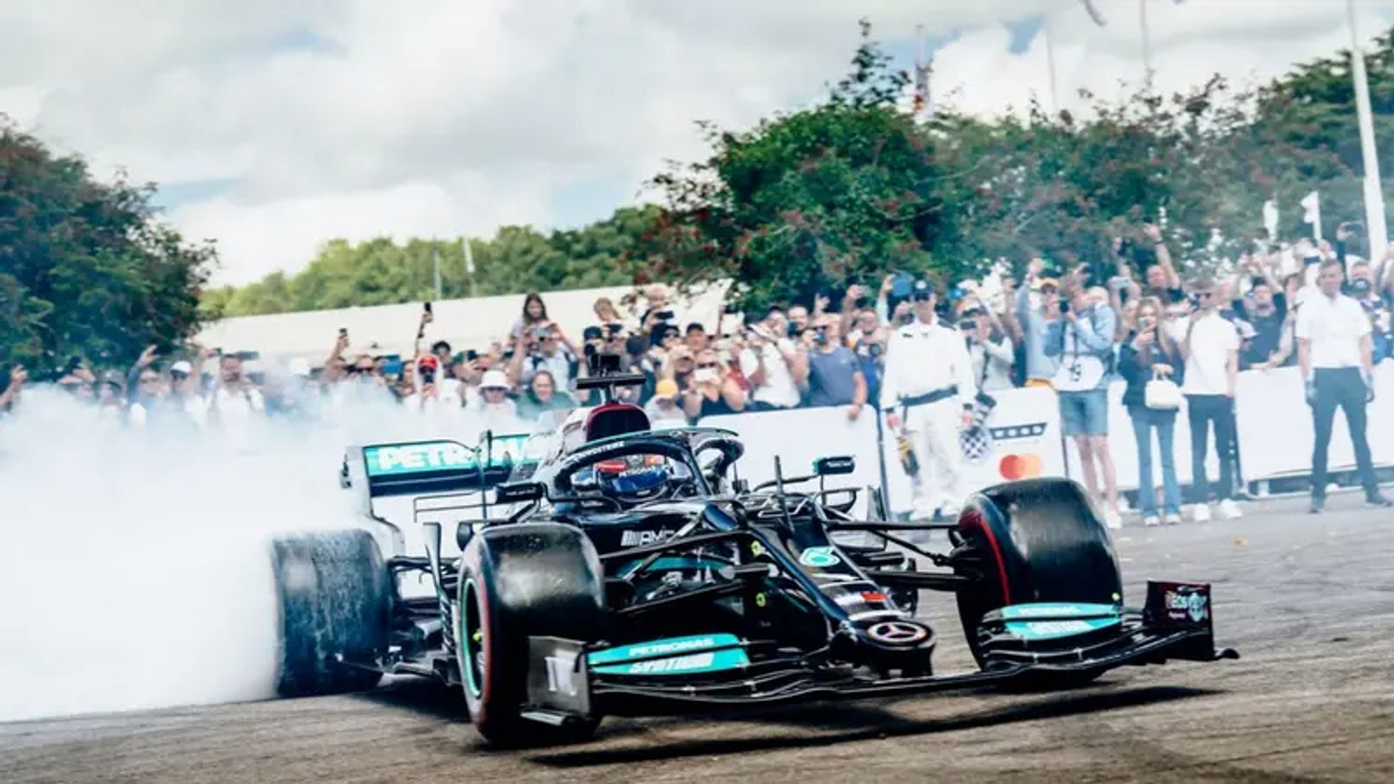
Another easily overlooked factor is ride height. If the ground clearance is too low, the boundary layer can "choke" the diffuser inlet, inducing premature flow separation.
This is why the ride height of an FSAE car must be meticulously calibrated—low enough to maximise ground effect, but high enough to prevent boundary layer choking.
The diffuser also boasts an underrated benefit: an exceptionally high lift-to-drag (or downforce-to-drag) ratio. Provided there is no severe flow separation, the diffuser itself contributes very little direct drag.
This means every kilogram of downforce generated comes virtually drag-free. In contrast, a rear wing produces downforce at the cost of significant induced drag.
This explains why F1 and LMP race cars rely so heavily on their underbody to generate downforce; while wings supply the remaining load, the diffuser operates at a much higher aerodynamic efficiency.
All previous discussions assumed that the car body is fixed. But what if the car body parts can move?

Active grille shutters are the most common active aero devices on production cars today.
During a cold start, the shutters close to block airflow to the radiator, reducing drag and helping the engine warm up faster. At cruising speeds, they adjust based on cooling demands, closing to clean up the airflow at the front end.
On the Lotus Eletre, closing the active grille shutter adds up to 15 km of driving range while generating 22.5 kg of downforce.

The active rear spoiler is another prime example.
The unit on the Lotus Eletre features four-stage adjustment: a low-drag setting at a 23° angle, and an optimum downforce setting that delivers 112.5 kg of downforce.
The Lotus Emeya takes this further with an active dual-stage rear spoiler spanning 296 mm, capable of generating 215 kg of net downforce, contributing to a total vehicle downforce exceeding 150 kg.
Working alongside an active rear diffuser, the Emeya seamlessly transitions between a low 0.21 Cd drag coefficient and high-downforce modes.
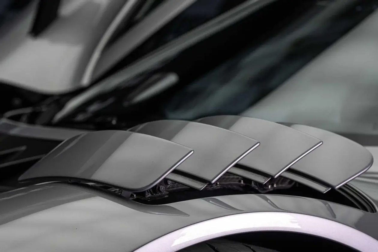
The core philosophy of active aerodynamics is real-time adaptation to driving conditions. At lower speeds where downforce is unnecessary, the system minimises drag to maximise range; at high speeds or during cornering, it increases downforce to enhance stability.
This logic is crucial in the EV era: every 0.01 Cd reduction in drag coefficient extends highway range by roughly 5 to 8 km. The slickest production sedans have now achieved a drag coefficient as low as 0.191 Cd.
Behind this figure lies countless hours spent by engineers optimising invisible elements like boundary layers, separation points, and pressure distribution.
Let's return to the falling paper analogy from the beginning.
The paper falls slower when flat because the pressure differential between its top and bottom surfaces creates drag.
Every breakthrough in automotive aerodynamics—from managing boundary layer transition and delaying flow separation to optimising diffuser angles and incorporating active rear spoilers—is aimed at the same goal: allowing air to flow over the bodywork with minimal disruption and accumulation.
While simple in concept, achieving this requires decades of relentless engineering and CFD analysis. Behind every production vehicle boasting a drag coefficient below 0.20 Cd is a masterclass in managing boundary layers, separation points, and pressure distribution.
References:
APS Division of Fluid Dynamics, “On the origin of the drag force on golf balls” (2017)
NRC Publications Archive, “New results from the evaluation of drag reduction technologies for light-duty vehicles” (2026)
Car and Driver, “The Physics of Diffusers: How to Make a Car Really Suck”
F1Technical, “The Ground Effect”
Born To Engineer, “The Engineering Behind Formula 1” (2025)
White, F. M., “Viscous Fluid Flow” (McGraw-Hill)
Schlichting, H., “Boundary-Layer Theory” (Springer)
Anderson, J. D., “Fundamentals of Aerodynamics” (McGraw-Hill)
SAE International, “Numerical Three-Dimensional Study of an Open Wheel Race Car Undertray” (2018)


Your go-to source for all things automotive in Malaysia. 🚗 Latest reviews, breaking news, launches & industry trends.
+ Follow This weekend is your chance to own a Volvo Selekt Certified Used Car, priced from just RM 148,000.
What are you waiting for?
#volvo 1 minute ago
This weekend is your chance to own a Volvo Selekt Certified Used Car, priced from just RM 148,000.
What are you waiting for?
#volvo 1 minute ago  We saw this accident this morning, and here’s a reminder to everyone: please drive safe. 2 days ago
  The G50 BMW 3 series is now here, adopting much of the i3's design elements.
So, where's the BMW M3?
#bmw #BMW3Series 4 days ago
The G50 BMW 3 series is now here, adopting much of the i3's design elements.
So, where's the BMW M3?
#bmw #BMW3Series 4 days ago Get the latest car news first!
Your go-to source for all things automotive in Malaysia. 🚗 Latest reviews, breaking news, launches & industry trends.
This weekend is your chance to own a Volvo Selekt Certified Used Car, priced from just RM 148,000.
What are you waiting for?
#volvo 1 minute ago We saw this accident this morning, and here’s a reminder to everyone: please drive safe. 2 days ago The G50 BMW 3 series is now here, adopting much of the i3's design elements.
So, where's the BMW M3?
#bmw #BMW3Series 4 days ago  ProtonGWMVolkswagenJAECOOVolvoPeroduaToyotaHondaTESLAMitsubishiMazdaJetourCheryBYDLexusBMWMercedes-BenziCAURZeekrIsuzuNissanLeapmotorPorscheFordOMODAMINIMGSuzukiXPengHyundaiWulingKiaSubaruDenzaGACLand RoverDongfengCAMAudiPeugeotFotonMAXUSsmartDaihatsuJACJMCMaseratiLotusAlfa RomeoRenaultGolden DragonKaiceneSeresLamborghiniFerrariJeepRolls-RoyceLepasAston MartinMcLarenChevroletBentleyFiatBAICForthingGeelyRoeweAeolusChanganARCFOXDeepalExeedHongqiVoyahJaguarKGMBuforiAcuraCadillacDodgeAbarthINEOSMHEROJMEVFreelander
© 2024 Bitauto.com. All Rights Reserved.
Bitauto (www.yiche.com and www.bitauto.com) is one of the most visited automotive websites in China. We provide detailed info on Chinese car brands available in your area. Please note that the information provided on this website is based on publicly available data and is for reference only. It may not be fully updated or accurate at all times.
Help us improve our website


